![]()
Home | Introduction | Magnetic Fields | Magnetic Force | Stored Energy in Magnetic Fields | Magnetism on the Sun | Further Exploration | Bibliography
![]()
Where q is the amount of charge, v the velocity of the particle, B the magnetic field, andFmag = qvBsin(1)
If you are familiar with vectors and vector math, in particular the cross product, the magnetic force equation can be expressed in a more elegant form in SI units as:
In circuits, electrons, which have a negative charge, are moving through the wires. This flow of electrons, a unit charge per unit second, is called current. As a result of this current, magnetic fields are created around wires. Hans Christian Oersted (1777-1851) stumbled upon this phenomenon after a lecture that he had given. He observed that if a compass was placed parallel to a wire with flowing current, the compass needle would deflect. Perhaps the reason why magnetic force was not detected in wires until Oersted is because of the large amount of current needed to create a measurable magnetic force. The relative weakness of magnetic force, compared to electric force that arises out of the presence of electric charge, can be seen in the next experiment with a wire coil and magnet.Fmag = qv x B
Force between a wire coil and magnet: The fact that moving charges create magnetic force can be seen in a wire coil with current flowing through it and a magnet.
Equipment:Applying this idea to the Sun, we see that magnetic fields and force arise out of the movement of charges through its highly conductive plasma, just as magnetic fields and force arose out of the movement of current through the coil.Thick magnet wire for the coil (around #20 gauge)Assembly:
Thin magnet wire that is light and flexible (around #36 gauge)
A Magnet
Power supply
Stands (to hold the coil)
Thread (to suspend the coil from the stand)
Wires with alligator clips
Graph paper
A flat surface such as a textbook (should be able to hold the graph paper vertical)Procedure:
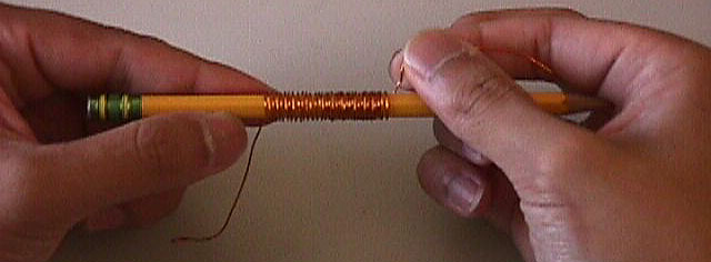
Wrap the thick magnet wire around a cylindrical object such as a pen and count the number of turns made. Make thirty to forty turns. Be sure that the wire is wrapped evenly. Record the number of turns.- Trim the ends of the wire so that they are about the same length. Burn off the enamel on the ends by passing them through a lighted match. Another way to remove the enamel is by scrapping it off using a pair of scissors or pliers.
- Carefully remove the coil from the cylindrical object so that its shape is preserved.
- Tie one end of the string around the middle of the coil so that when suspended, it hangs horizontally. Tie the other end to the stand, suspending the coil.
- Remove the enamel on the ends of two thin magnet wires in the same way that enamel was removed for the thick wire. Connect an end of a thin wire to one end of the coil. Do the same to the other coil end with the other thin wire. This allows the coil swing easily without being restricted by heavy wires.
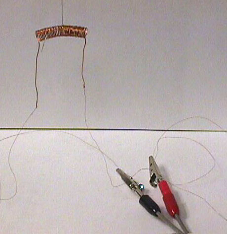
Connect a wire with alligator clips to one thin wire. Do the same with the other thin wire. Make sure that the thin wire is long enough, so that the metal of the alligator clips does not interfere with the magnet when it is brought up to the coil.
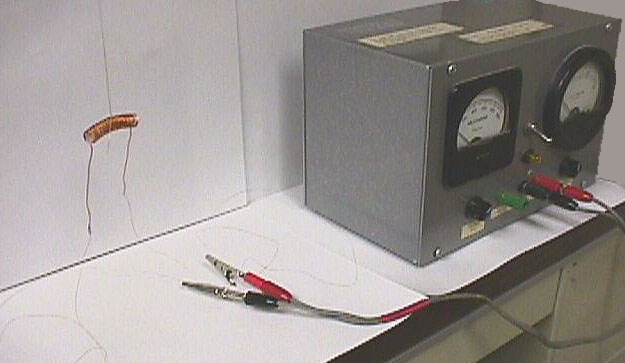
Connect the other ends of the wires with alligator clips to the power supply, forming a circuit.- Tape the graph paper to the flat surface and stand the surface up behind the coil. With a pencil, place a mark on the graph paper directly behind the right side of the coil. This allows us to measure the distance the coil has moved when a magnet is placed next to it.
Calculations:
- Turn on the power supply. Turn the current up to one ampere or the highest setting if one ampere cannot be reached. A current will flow through the coil, resulting in a magnetic field.
- Bring a magnet close to the right end of the coil. Does the coil repel or attract?
- Orient the magnet so that the coil is attracted to the magnet. Being careful to see that the thin wires are not pulling the coil, pull the coil to the right from its initial position using the magnet. Place a mark on the graph paper at the location of the right side of coil where the coil falls away. Also write the amount of current being provided by the power supply next the mark.
- Decrease the amount of current provided by the power supply. Repeat steps two and three. Continue decreasing the current until a satisfactory number of measurements are made.
- If you have extra magnet wire, make another coil, this time with a fewer number of turns and conduct the same experiment (steps one through four) as before.
Using the data obtained from the experiment, plot a graph showing the magnetic force versus the amount of current provided. Determine the relationship between these two variables (Hint: the current is related to qv in Equation 1). Is the magnetic force directly proportional to the current? Also, if more than one coil was made, establish a relationship between the number of coils and the strength of the magnetic force.What's Going On?According to Equation 1, Fmag = qvBsin
![]()
 Return
To Activities
Return
To Activities |
 |
 |
 |
 |
 |
 |
 |
||||
 |
 |
 |
 |
Last revised by Eugene on August 26, 1999